
Birth of the Hippogriff
(How I Started on the Slippery Slide to Building a Special)
By Cliff King
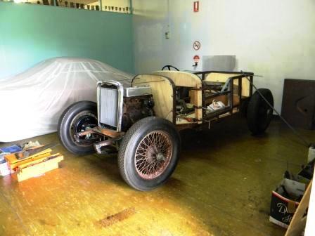
After
Before


The name ‘Hippogriff’ was coined by Ken Swinbourne.
In February/March 2007, I was at a loose end. I was in early retirement and the rebuild of the XK140 had concluded with registration the previous year. It was apparent that time was passing slowly as acknowledged by my MD.
Luckily for all around me, an advertisement in the “Oily Rag” the HSRCA publication, had caught Rob Rowe’s attention.
The ad was placed by Ray Finch in South Australia and detailed a bunch of rusty bits that hinted at the possible build of a ‘special’. Ray was well known for his re-creation of SS Jaguars using appropriate bits, but had decided to retire prior to attempting yet another. The ad was the result and Rob kindly drew my attention to the advertisement.
I called Ray and did the deal, setting out for S.A. in early March. The weather was very hot, and at the bidding of ‘Murphy’, the air conditioning on my wagon decided to pack it in shortly after leaving Sydney. Packing up the trailer at Ray’s workshop was an experience, but after some perseverance I set off for NSW.

The photo above shows the trailer en-route to NSW, heavily laden with the bits.
Rob had agreed that I could store and work on building the special at his Riverstone workshop, so it was to there that I delivered the bits. They were:
- a chassis
- a gearbox
- 5 wire wheels
- front and rear suspensions
- two Meadows engines
- some brake drums
Assessing what you have
As those who have gone this way well know, the first thing to do is assess what you have.
- The chassis was described as from an early 1930s Standard, but no identification was immediately apparent.
- The suspension units were either late Jaguar SS or early 1940s Jaguar, sometimes referred to as MKIV models, a description not used by the factory.
- Wheels and brake drums were also Jaguar, but their size hinted at the 1 ½ litre model.
- The Meadows engines had excited my interest, but eventuated to be from lifeboats, possibly WW2 vintage - certainly no good for my purpose with the possible exception of an Lucas vertical magneto with impulse start mode.
Unloading the rusty bits was a journey in itself. Given the suspected age of the chassis and other bits, it was surprising just how good the South Australian rust was. Sure, some bits were frozen but overall no holes, merely a film of corrosion.
November 2011
Identifying the chassis
One of the first tasks (apart from cataloguing what I had acquired) was to identify the chassis. The gearbox ID was easy, cast into the side of the box was the word “STANDARD”. It appeared that the box was a mate to the chassis based on the configuration of the bell housing and rear mount…a half round piece on the gearbox and mating shape on the chassis.
I measured the wheelbase and track as best I could and went through Georgiano’s book of English cars (kindly lent by Andrew Hyden) for a match. Standard appeared to be the closest and Rob meantime, had discovered a number stamped on the front rail. The Standard Car Club in the UK has details of the various models’ specifications on their website and from that data it appeared that the chassis was from a 1934 Standard 9. This was confirmed in an email from the club.
Other distinguishing features of the chassis were cruciform bracing in the middle, and the underslung rear rails. These features suggested why Ray Finch had planned to use it to produce another replica, as those features were present on the chassis Standard produced for Standard Swallow for one of their SS models of the era.
At this stage of the proceedings, I had no firm plans as to what style of special would be formed, other than it needed to appear post vintage.
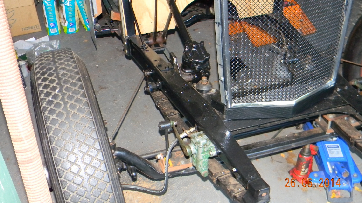
The first step, however was to make a cohesive rolling chassis from the bits. The Jaguar front and rear suspensions are about 4 “ wider than the Standard version, requiring some modifications. Rob’s idea for this was to use a 16mm adaptor plate to move the Jaguar U bolt attachment points in to meet the Standard front springs. The rears were more simple requiring moving the Jaguar rear axle mountings appropriately.
As expected, the springs had seen better days and were re-made. Front shackle pins were made from shoulder bolts and spring centre bolts from cap screws. Spring shackle bushes are polyurethane. The front shackle bushes are bronze, and were reamed to suit the shoulder bolts.
The chassis was wire brushed, treated with an inhibitor and painted with black semi gloss enamel. I put a measure of Penetrol into the enamel. This helps the paint flow and (I believe) provides some flexibility. As the chassis and build generally is constructed of old parts, a glossy finish would, in my opinion, look out of place.
Careful measurements were taken after the springs and front suspension was fitted to ensure things were in alignment. To my frustration, I couldn’t get the distance from the shackle pin on one side, equivalent to the other. Parts were dismantled, checked for damage, all to no avail.
Finally, I thought to compare the distance from the shackle pin on one side to the centre bolt. Bingo, the spring centre bolts were not equidistant…back to a spring manufacturer who is now, no longer in business.

November 2011
With the chassis more or less set in its desired state, the wheels, 18” 60 spoke affairs, were installed with new hub bearings and cotter pins retaining the king pins.
The king pin bushes were in surprisingly good condition, as were the splines on the hubs. New hub bearings were fitted, all are still available.
The braking system exercised the grey matter somewhat.
The Jaguar system used Girling wheel expanders, cast from ‘pot’ metal. The expanders were activated by rods, and to all accounts were very effective. 12” finned cast iron drums certainly helped to retard the largish saloon.
The problems were;
- The expanders were severely corroded, and while electrolysis removed rust from the steel innards, the exteriors were generally unuseable.
- The front axle/spring configuration that had been married to the 1934 Standard 9 chassis would not allow the front wheel Jaguar mechanism to be fitted.
I called Ed Nantes, Jaguar SS guru in Melbourne, who fortuitously knew of a person who had cast the Girling expander bodies in bronze. Luckily, this guy had a full set available at a great price and there remained some machining to be done, to fit the innards. For the front brakes, I decided (with help from my ‘mechanical adviser’ ) to opt for hydraulics. Suitable Holden wheel cylinders were inserted in the backing plated and connected.
The brakes originally fitted to the Standard 9 chassis were operated by cable. However the cross-shaft was adaptable to firstly, connecting the rod to actuate the mechanical rears, and secondly a pushrod to activated the master cylinder for the fronts. The master cylinder was attached to a bracket bolted to a convenient cross-member.
The challenge in this system, will be suitable adjustment to achieve front/rear balance. I have a little experience in this matter albeit some 50 odd years ago. Then, I fitted Morris 840 hydraulic front wheel cylinders into the backing plates of my Austin 7, parts obtained from John Grant’s father’s wrecking yard in Carlton. The composite hydraulic/mechanical system was much more effective than the original set-up.
The brake drums were in ‘period’ condition and were immeasurably improved by derusting, skimming and balancing. The latter process made necessary by the occasional absence of finning.
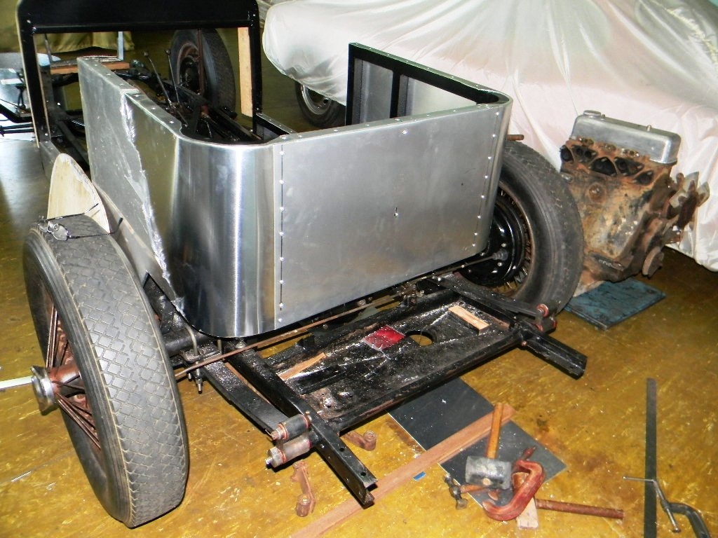
Next step was the body.
Now it happened that Rob had languishing in the back of his workshop, a body frame that had been fabricated by Bob Winley for John Medley’s Alvis race car. Or so the story goes.
In any event this was in 3 parts, frame and two doors. Made from 40mm square section tube, it’s a tub arrangement, looking suitably vintage.

2012
Surprisingly, this frame was the right configuration to bolt up to the chassis. It did require fabrication of a scuttle frame and hinges to fit the doors. The latter were made from 5mm steel plate and hollow bar for the pins. Doors and ‘A’ pillar had been fitted with tapped plates to aid attachment of the hinges.
Following fabrication of the scuttle frame, I laminated a wooden piece to form the backing for the dash and aluminium cladding. The latter was formed up from sheet and with the help of a well known expert body builder, shaped to fit the curved scuttle, complete with returns front and rear.
The plan was to clad the body with aluminium.
The frame had subtle curves that were deemed to be suitable for cladding without the use of a ‘wheel’.the theory being that the aluminium would follow the curves without distortion. I made up cardboard patterns for the sides and back, and proceeded to cut the pieces to size with an angle grinder fitted with a 2’’ cutting disk. I had been advised that this was the best method, provided the disk was first coated with soap as a lubricant. It worked well, but noise and metal particles abounded!
I’m biased, but I believe the cladding process went satisfactorily. On the bottom of the body, the cladding was hammered around the frame and on top of the frame (top of the tub and door openings) countersunk pop rivets completed the attachment. The top areas were also finished with a 38mm wide cover strip. The challenge here, was to bend the 38/5mm thick strip around the rear of the tub.

2012
I tried to bend the strip initially with the help of a jig and copious clamps. No way!! And I was convinced the task was impossible. Enter the aforementioned ‘expert body builder’ who showed me how. Holding a liece of strip on its edge in the vice. He applied heat, while applying pressure. He explained that the metal would start to give when hot enough and so it did. Some shaping was necessary to smooth out the distortion that occurred with the stretching of the outside curve and inside shrinking, but it worked. I was able to duplicate this process to a certain degree, but it won’t hold too much scrutiny. Notwithstanding my amateur efforts, I felt much satisfaction in achieving what I had felt impossible.
The bonnet was the next challenge.
Not having a radiator grill, I settled on a Jaguar Mark VII frame. This had been attached to the chassis. I constructed a ‘buck’ and tried to shape the aluminium around it. No success, the metal was half hard and I failed in my attempts to anneal it due the lack of a suitable heating medium. Another club member had been using the services of a skilled sheet metal worker in St. Marys and so I took the so called buck and sheet aluminium to his workshop, Using some rollers and constant reference to the buck, a passable bonnet was formed. This was in one piece, and subsequently, with a good degree of confidence, I cut it down the middle with my trusty angle grinder without stuffing it up.
Rob Phillips assisted me in riveting a stainless hinge in the middle. Nothing like the skills of ta long time experienced aircraft engineer to complete a task!!
2014
The engine
The post war Jaguar 4 cylinder engine, was a run on from the pre war SS. Designed and manufactured by Standard Cars for Jaguar commencing in 1937 it powered the pre and post war 1 1/2 litre saloons. Although called 1 1/2 litre, the capacity is really around 1.75 litres. Jaguar’s contribution to the design was an overhead valve conversion, the Standard ’12’ version retaining side valves.
The design followed some features that were standard for the 4 cylinder engines produced by that maker. It was desaxe and the big ends were offset.
Wikipedia describes it thus
“A desaxe engine, is one in which each cylinder is positioned with its exact center (the bore axis) slightly offset from the center line of the crankshaft. "Désaxé", in French, means "unbalanced". The article goes on to describe this concept in more detail, well worth reading.
Post war, the term SS had unpleasant connotations and Jaguar production vehicles took the company name. Incidentally, the name ‘Jaguar” was first seen in 1936, appearing beneath the SS descriptor.
Captain Black from Standard offered Lyons the 6 cylinder manufacturing line at such a good price that it is alleged Lyons sent someone around immediately with a cheque. Black kept the 4 cylinder line and produced a range of Triumph cars commencing with the Triumph 1800. Thus after 1948 there were no 4 cylinder Jaguars produced.
I mentioned in a previous part, the process by which I acquired the Jaguar engine. At first appearance, it gave cause for confidence. It turned over easily and showed no visible signs of damage. It was coated with a ‘concretion’ of dirt and clay that was hard to remove. So, I commenced disassembly. Immediate findings were that the valves were worn, one pushrod had been welded and the block sleeved. The latter was initially worrying till I discovered that the 4 cylinder blocks were sleeved at manufacture. A bigger disappointment was the discovery that a piston circlip had come loose resulting in the gudgeon pin ‘tramlining’ the bore.

2014
As expected, main and big end journals were worn, and the camshaft bearings/journals were out of specification.
Locating replacement bearings was a problem. Mains and thrust bearings were sourced through Automotive Surplus in Melbourne, but locating big ends defied al attempts. Through word of mouth I found out that MGA and MGB bearings were a similar size, merely requiring a slight resizing of the big end tunnel.
Sleeves for the bore were another problem, but eventually some reasonably sized sleeves were obtained from Repco. The block had to be honed and the sleeves machined to suit, as well as to provide a small locating top flange. They were pulled in using a 3/8” threaded rod.
All reciprocating parts were crack tested, with satisfactory results. The cylinder head was overhauled by Rams at Windsor. They skimmed .080 from the surface to eliminate cracks, and fitted the NOS valves that I had acquired from Ed Nantes in Melbourne. Valve guides are solid bronze. Springs are Isky (half of a V8) and one spring replaces 3 originally fitted i.e., double springs on the valves and one spring on the pushrod immediately above the tappet block.
The new block sleeve bore turned out to be a similar size to a 4 cylinder Volvo and new solid skirt replacements were obtained from JP in Adelaide.
The block, crankshaft, rods, camshaft etc were supplied to Duncan Foster (DF) at Blacktown for machining. Replacement cam bearings were another unobtainium so DF manufactured appropriately sized ones from bronze, after finishing the camshaft.
Assembly, as Jaguar oft states in their manuals, is the reverse of disassembly!!
Reading this, it appears that all went smoothly with a few minor glitches in sourcing parts. The written word blandly ignores the many hours spent in research, phone calls, pouring over catalogues and manuals in an attempt to solve the many issues that arise from the re-build of an old motor. But I guess many of you have been down that road.
Thanks go to ...
Thanks go to Rob Rowe for his valuable assistance with resolving engine issues and Ed Nantes a stalwart of the VSCC in Melbourne, well known a s a SS expert. Duncan Foster were very cooperative with the engine rebuild, and from the various engines that I saw in their workshop, its clear that my job was a small one of many.
Historical sources
- “Jaguar” a Biography, Lord Montagu of Beaulieu, pub., Cassell London
- “Jaguar” The history of a great British car, Andrew Whyte pub., Patrick Stephens, Cambridge for Jaguar Cars Limited.
Assembled engine sans head complete with XK120 gearbox